|
 The
Starlight
Xpress MX516 Monochrome CCD camera was the first CCD camera
that I owned. For its cost its performance was very good. The
Starlight
Xpress MX516 Monochrome CCD camera was the first CCD camera
that I owned. For its cost its performance was very good.
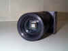
The MX516 is extremely compact. In fact it has been called
the 'eyepiece camera' because it can be placed directly into a 2
inch eyepiece holder. It uses the Sony ICX055AL chip
which provides a reasonable 500x290 pixels (4.9x3.6mm) or a FOV of
8x6 arcminutes on a LX10. It attaches to the PC's parallel
port by means of a single cable. There are no intervening
electronics. The camera comes with software that not only
controls the operation of the MX516 but can perform most of the
basic
image processing tasks. The camera has very
low dark current. I have taken images well in excess of 1
minute without the need to subtract a dark frame. The camera also
has extremely good 'blue' response which makes it very suitable for color imaging. For me, the MX516 worked first time right out of the box.
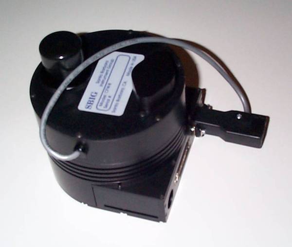
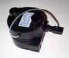 The
SBIG ST-7E CCD Camera
is much more expensive than the Starlight Xpress MX516 but has more
capabilities. It uses the Kodak KAF-400E chip which has
764x510 9 micron square pixels (6.9x4.6mm). This gives the
ST-7E a larger FOV than the MX516. However, the real
differences between the ST-7E and the MX516 are self-guiding,
image binning and programmable cooling capabilities. The
SBIG ST-7E CCD Camera
is much more expensive than the Starlight Xpress MX516 but has more
capabilities. It uses the Kodak KAF-400E chip which has
764x510 9 micron square pixels (6.9x4.6mm). This gives the
ST-7E a larger FOV than the MX516. However, the real
differences between the ST-7E and the MX516 are self-guiding,
image binning and programmable cooling capabilities.
First, let's discuss self-guiding. The ST-7E has a second
CCD chip mounted underneath the KAF-400E. This second chip, a
Texas Instruments TC-211 with 192x164 13.75x16 micron pixels
(2.64x2.64 mm), can be used to autoguide the telescope while the
KAF-400E is imaging. You can buy add on hardware for
the MX516, called STAR2000 which lets the MX516 selfguide but this
works in a different way. The MX516 uses the same chip to
guide and image. This allows you to guide on a star within the
same FOV as your image but has the disadvantage that exposure
durations are doubled because half the time of the CCD chip is spent
guiding instead of collecting those all important photons for your
image.
Now lets look at image binning. Binning is the ability of
the camera to combine several pixels on the CCD chip to create one
big pixel. The ST-7E allows you to create an 18 micron square
pixel from four 9 micron square pixels (known as 2x2 binning) or a
27 micron square pixel from nine 9 micron square pixels (known as
3x3 binning). Clearly the resolution of the chip is reduced to
382x255 with 2x2 binning and to 255x170 with 3x3 binning. Why
would you want to trade resolution for pixel size? The
simple answer is exposure duration. An 18 micron square pixel
has four times the area of a 9 micron square pixel and consequently
will collect 4 times as many photons in the same amount of time.
This means that exposure durations are cut by a factor of 4 with 2x2
binning and by 9 with 3x3 binning. This feature can be
particularly useful when producing color images using the LRGB
technique. With this technique, only the L or Luminance
image needs to be taken at full resolution. The R, G and B
images can be taken at a much lower resolution without sacrificing
the resolution of the final color image. By taking the R, G
and B images using 2x2 or 3x3 binning you can reduce the total
exposure duration significantly compared to taking these images at
full resolution.
Finally, lets look at programmable cooling. The ST-7E has a
cooler that can cool the CCD chip to 30 degrees C below the ambient
temperature. This is essential to reduce the dark current
produced in the CCD chip which shows up as noise on your CCD image.
However, even cooling the chip to 30 degrees C below ambient will
not stop dark current noise building up in your image during a long
exposure. Fortunately, the dark current produced is
always the same for a given chip temperature and exposure duration.
This means that we can take an image of the dark current,
known as a dark frame, and remove the noise from the original image
simply by subtracting the dark frame. The dark frame is
created by taking an image with the camera shutter closed. To
ensure the same dark current is produced as in the original image
the dark frame must be of the same length and be taken at the same
temperature as the original image. The ST-7E can be
programmed to cool the CCD chip to a given temperature and then keep
it there as long as the chosen temperature is not less than 30
degrees below ambient. Why is this useful? With the
MX516, the dark frame must be taken soon after the image to ensure
it has been taken at the same temperature. With the ST-7E you
can take the dark frames any time you want to as long as you program
the camera to cool the CCD chip to the temperature at which the
original image was taken. This means you can take the dark
frames the next day and not waste valuable imaging time imaging the
back of your camera shutter! You can even build up a
library of dark frames with different durations and temperatures. I have
noticed that the ST-7E produces a higher level of dark current than
the MX516 for a given temperature. However, this
is not a significant disadvantage as the dark current is easily
removed using dark frames and the design of the ST-7E makes it very
easy to produce them.
The overall quantum efficiency (sensitivity) of the ST-7E seems
to be higher than the MX516. This leads to shorter exposure
durations. However, the sensitivity of the ST-7E to blue
light is about half its sensitivity to red and green light.
For color imaging, this means images taken through the blue
filter need to be twice as long as the the images taken through the
red and green filters. In contrast, the MX516 has a much more
uniform sensitivity across red, green and blue wavelengths leading
to roughly equal exposure durations through each filter.
One other difference between the MX516 and the ST7E is the
shutter. The MX516 has an electronic shutter whereas the ST-7E
has a mechanical shutter. The mechanical shutter of the ST-7E
enables dark frames to be taken very easily as you simply close the
shutter and take an image. With the MX516 you have to cover
the telescope OTA or close the mirror in the flip mirror.
However, the mechanical shutter does mean that the shortest
possible exposure is 0.1s compared with 0.01s for the MX516.
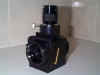
I
purchased the
SBIG ST-2000XM CCD Camera
in November 2005. It has similar functionality to the ST-7E but has
a larger, higher resolution chip. The ST-2000XM uses the Kodak
KAI-2020M CCD chip. This is 11.8 x 8.9 mm and has 1600 x 1200
7.4 micron pixels. It also features a TC-237H chip as the
tracking CCD which has 2.7 times the area of the tracking CCD used
in the ST-7E. This increases the chance of finding a suitable
guide star without having to adjust the position of the camera on
the telescope. The ST-2000XM also has a USB connection to the
PC which makes image download a lot faster than the parallel cable
connection on the ST-7E. I chose the ST-2000XM over the
ST-8XME because I wanted an ABG camera with a large, high resolution
chip. The ST-2000XM's ABG chip has a higher sensitivity than
the ABG version of the ST-8E and is higher resolution with only a
slightly smaller chip. It also costs $1000 less!
In 2008 I
purchased the
SBIG STL-11000M CCD Camera
. It has similar functionality to the ST-2000XM but has
a much larger chip. The STL-11000 has a 35mm chip with
4008x2672 9 micron pixels. The Kodak chip used is similar in
sensitivity to the ST-2000XM but its 9 micron pixels mean that
overall it is approximately 50% more sensitive. This camera
also has a built in filter wheel that will accept 5 50mm filters.
In all other respects the camera is very similar in features and
operation on the ST-2000XM.
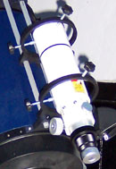
The
SBIG CFW8 filter wheel can be attached directly in front of the
ST-7E (as shown) or to the MX516 via a T-ring connector. It is
a motorised filter wheel that holds up to 5 1.25 inch filters and
comes complete with a set of clear, red, green and blue filters for
colour imaging. The red, green and blue filters have an
infra-red (IR) blocking coating which means you don't need an
additional IR filter placed permanently in the optical path.
This has an added advantage when using the LRGB colour imaging
technique. With this technique, the L or Luminance image is a
CCD image taken through a clear filter. It should be the
longest duration image as it is the one that will provide the detail
in the final colour image. Unike the R, G and B images it does
not have to be taken with an IR filter in place. An RGB filter
set that relies on a separate IR blocking filter in the optical path
will result in the L image being taken through a clear filter/IR
filter combination. This will lead to a longer exposure on the
L image as the IR light is blocked. The CFW8 filter does not
require a separate IR filter and so the L image duration is lower.
The CFW8 comes with its own DOS based control software but I
have used MaximDL to control it. When attached to the ST-7E, the wheel is
controlled through the ST-7E parallel cable attached to the PC.
When it is attached to another camera it is controlled via the
serial port of the PC. With the CFW8 and MaximDL you can
set up an RGB exposure sequence and leave it to run unattended.
Once each image is completed MaximDL instructs the filter wheel to
move the next filter into position and then starts the next image.
Being able to set up an automatic sequence like this, with a very
small delay between each filter change, is valuable for colour
imaging of Jupiter where the fast rotation of the planet means you
only have a few minutes to take all three RGB images to avoid
blurring due to the planet's rotation.
The Canon 10D Digital SLR camera is quite capable of producing
good quality images of the brighter deep sky objects and is very
good for Solar, Lunar and Planetary imaging. With it's big
CMOS chip (23x15mm) and high resolution (3072x2048 7.4 micron
pixels) it is an excellent camera for wide field imaging and for
capturing the entire Lunar or Solar disk in one image even at
relatively long focal lengths (1575mm). The fact that it
can take exposures as short as 1/4000th of a second allows Lunar and
Solar images to be taken without the need to stop down the LX200
10" SCT. With the TRC80-N3 timer you can take the long
duration exposures required for deepsky imaging. As the camera
is not cooled, exposure duration is limited to around 5
minutes. Much longer than that and the dark noise becomes
unacceptably high. However, by stacking multiple 5 minute
exposures together very deep images can be taken. An excellent
review of the Canon 10D SLR can be found on Johannes
Schedler's website
The Canon 40D Digital SLR camera is very similar
to the Canon 10D. The main differences are:
-
It has smaller pixels (5.7 microns) in
the same size chip giving a higher resolution of 3888x2592.
-
Power efficiency is greatly improved over the
10D. It's possible to take over 1 hour of 10 minute sub
frames with the 40D with the internal battery pack.
-
The LCD screen is much larger
-
It has a live view mode which can show you
the real time image of a star on the LCD screen. This
makes getting a good focus much easier than with the 10D.
The ToUCam Pro II Webcam is ideally suited for high resolution
planetary, lunar and solar imaging. It has a sensitive 640x480
CCD detector with 5.6 micron pixels and can capture a large number
of images very quickly in an AVI file. This makes it very
straightforward to collect a large number of short exposures of a
planet. A small percentage of these images (say 10%) will have
captured the best moments of seeing and so show the most
detail. As a large number of images will have been taken in
the AVI (say 2000), a fairly large number of good images will be
left (say 200) which can be added together to produce an image with
a very high signal to noise ratio compared to the original
image. If the 200 best images are added together, the
resulting image will have a signal to noise ratio 14 times higher
than a single image. This image can then be processed
with Unsharp Masking and Deconvolution software to yield high
amounts of detail. To attach the webcam to the telescope you
will need to unscrew the lens that comes with the webcam and replace
it with a T-ring adapter that lets you attach it to your telescope
accessories. You will also need to use an infra-red filter with the
webcam to get the correct colour balance when imaging. I
obtained my webcam, T-ring adapter and 1.25" infra-red filter
from True Technology.
The 1.25" filter screws into the T-ring adapter.
When taking images with the webcam it is important that you set
the frame rate low enough (5-10 frames per second) so that the
camera does not have to compress the image data as it is sent to the
computer. Compressing the image stream would mean you lose
some of the fine detail you wanted to capture!
To control the webcam you can use the software that comes bundled
with the camera. However I use Astrosnap
to control the camera as it has a number of useful features such as
focus aids and the ability to use the webcam to help collimate your
telescope.
A good review of the ToUCam Pro II and suggestions for exposure
and gain settings can be found here.
 The
Takahashi FS-60C is an f/5.9 60mm Apochromatic Refractor. It
has a focal length of 355mm, which makes it a very good telescope
for wide field imaging. The focal length can be reduced to
270mm and the f-ratio decreased to f/4.5 by adding a Takahashi Sky 90
focal reducer. This increases the field of view still further,
produces a flat star field even on large format CCD chips and lowers
the exposure times required. Apochromatic refractors make excellent telescopes for colour imaging
as they do not suffer from the chromatic aberration inherent in
chromatic refractors. Chromatic aberration is where the
telescope brings different wavelengths of light to a focus at
slightly different points resulting in colour fringing around
objects. I obtained my Takahashi FS-60C from True
Technology. I have used it mounted piggyback on the LX200
and RCX400 using
mounting rings and rails made by BC&F. The
Takahashi FS-60C is an f/5.9 60mm Apochromatic Refractor. It
has a focal length of 355mm, which makes it a very good telescope
for wide field imaging. The focal length can be reduced to
270mm and the f-ratio decreased to f/4.5 by adding a Takahashi Sky 90
focal reducer. This increases the field of view still further,
produces a flat star field even on large format CCD chips and lowers
the exposure times required. Apochromatic refractors make excellent telescopes for colour imaging
as they do not suffer from the chromatic aberration inherent in
chromatic refractors. Chromatic aberration is where the
telescope brings different wavelengths of light to a focus at
slightly different points resulting in colour fringing around
objects. I obtained my Takahashi FS-60C from True
Technology. I have used it mounted piggyback on the LX200
and RCX400 using
mounting rings and rails made by BC&F.
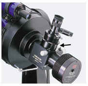
 The
True Technology Flip Mirror Finder and Filter Holder serves two
purposes. The first is to act as an aid in centering and
focussing an object for a CCD camera. It does this by putting
a movable mirror in the light path from the telescope to the CCD
camera. When the mirror is down, the light passes through to
the CCD camera as normal. When the mirror is inclined at 45 degrees,
the light is diverted away from the CCD camera and into an eyepiece.
This allows the observer to see exactly what the CCD camera is
looking at without removing the camera. It is possible to
adjust the position of the eyepiece so that it is parfocal with the
CCD camera. This means that an approximate focus for the
camera can be found very quickly by first focussing the object in
the eyepiece. This has dramatically reduced the time it takes
me to focus the camera. Once the object is focussed in the
eyepiece, taking a small series of images with slight focus
adjustments in between each one will bring the camera to perfect
focus. A side benefit of the moveable mirror is the ability to
take CCD dark frames very easily. Simply move the mirror to the 45
degree position and all light is cut off from the CCD enabling a
dark frame exposure to be taken. The
True Technology Flip Mirror Finder and Filter Holder serves two
purposes. The first is to act as an aid in centering and
focussing an object for a CCD camera. It does this by putting
a movable mirror in the light path from the telescope to the CCD
camera. When the mirror is down, the light passes through to
the CCD camera as normal. When the mirror is inclined at 45 degrees,
the light is diverted away from the CCD camera and into an eyepiece.
This allows the observer to see exactly what the CCD camera is
looking at without removing the camera. It is possible to
adjust the position of the eyepiece so that it is parfocal with the
CCD camera. This means that an approximate focus for the
camera can be found very quickly by first focussing the object in
the eyepiece. This has dramatically reduced the time it takes
me to focus the camera. Once the object is focussed in the
eyepiece, taking a small series of images with slight focus
adjustments in between each one will bring the camera to perfect
focus. A side benefit of the moveable mirror is the ability to
take CCD dark frames very easily. Simply move the mirror to the 45
degree position and all light is cut off from the CCD enabling a
dark frame exposure to be taken.
The second purpose served by this device is that of a filter
holder suitable for color imaging. The unit comes with
four rectangular metal plates. You can screw a standard 1.25
inch filter into each plate. A plate/filter assembly can then
be inserted into a slot in the filter unit which is just in front of
the adjustable mirror. You can remove and insert plate/filter
assemblies without changing the position of the camera or focus of
the telescope. As well as the slot for filters, the unit also
allows a 1.25 inch IR filter to be permanently mounted in front of
the CCD camera. True Technology sells a set of 1.25 inch RGB
and IR filters suitable for color imaging with this unit.
The set comes with a clear glass filter which has the same thickness
as the color filters so that you can focus the camera before
inserting the color filters.
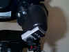
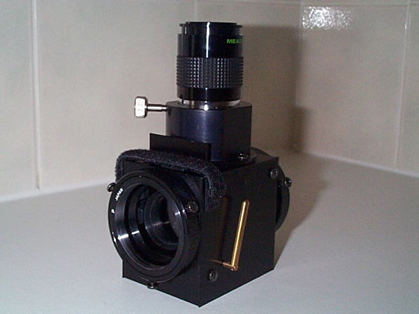
 The Meade
2 inch Flip Mirror is similar in functionality to the True
technology flip mirror above. It does not have the filter
holder but has a wider 2 inch aperture which it makes it suitable
for attaching CCD cameras and DSLRs with larger imaging chips
without causing vignetting. It also allows you to adjust the
flip mirror so that the image is dead centre in the eyepiece when it
is centered on the CCD chip. The flip mirror comes with a
number of different adapters for attaching CCD cameras. This allows
you to choose the adapter which puts the camera it at the right
distance from the flip mirror so that the eyepiece can be made
parfocal. A cylindrical focusser is provided to help you focus
the parfocal eyepiece. All the CCD camera adapters have
thumbscrews that allow you to loosen the adapter and rotate the
camera should you need to do so to frame an image or find a
guidestar. This is much easier than the True Technology flip
mirror where the adapter is attached via screws that need to be
loosened and tightened with a screwdriver. The Meade
2 inch Flip Mirror is similar in functionality to the True
technology flip mirror above. It does not have the filter
holder but has a wider 2 inch aperture which it makes it suitable
for attaching CCD cameras and DSLRs with larger imaging chips
without causing vignetting. It also allows you to adjust the
flip mirror so that the image is dead centre in the eyepiece when it
is centered on the CCD chip. The flip mirror comes with a
number of different adapters for attaching CCD cameras. This allows
you to choose the adapter which puts the camera it at the right
distance from the flip mirror so that the eyepiece can be made
parfocal. A cylindrical focusser is provided to help you focus
the parfocal eyepiece. All the CCD camera adapters have
thumbscrews that allow you to loosen the adapter and rotate the
camera should you need to do so to frame an image or find a
guidestar. This is much easier than the True Technology flip
mirror where the adapter is attached via screws that need to be
loosened and tightened with a screwdriver.
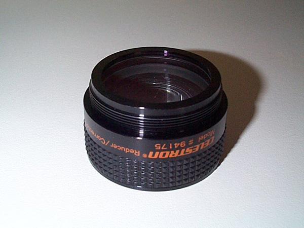
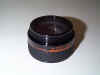 Attaching
the Celestron
f/6.3 focal reducer to the f/10 LX10 or LX200 reduces its focal
length by 37%. This gives an increased field of view both for
visual observations and CCD imaging (see What
Focal Length Should You Use?). Also, the shorter focal length
reduces the exposure times needed for CCD images by approximately
60%. Attaching
the Celestron
f/6.3 focal reducer to the f/10 LX10 or LX200 reduces its focal
length by 37%. This gives an increased field of view both for
visual observations and CCD imaging (see What
Focal Length Should You Use?). Also, the shorter focal length
reduces the exposure times needed for CCD images by approximately
60%.
The exact reduction in the focal length depends on the distance
of the CCD chip from the focal reducer. The reduction is
governed by the formula R=1-(D/F) where R is the focal reduction, D
is the distance of the chip from the reducer and F is the focal
length of the reducer. In other words, the further away the
CCD chip is from the focal reducer the larger the focal reduction
will be. In reality, the focal reducer is only designed to
work well when the chip is close to the distance that yields f/6.3.
At distances greater than the point which yields f/6.3 the image is
likely to suffer from vignetting. Vignetting is seen as
darkening around the edges of CCD image. It is caused when the
field of illumination of the telescope has been reduced to the point
where it is smaller than the CCD chip.
Looking at the separation of stars in my images I have calculated
the focal length of the reducer to be 298mm. This means f/6.3
is achieved when the chip is 110mm from the reducer. I have
taken images with the MX516, True Technology Flip Mirror and
Celestron OAG connected to the reducer. This setup places the
CCD chip approximately 150mm behind the reducer which results in a
focal reduction of R=0.5 or f/5. The SBIG ST-7E, CFW8 and True
Technology Flip Mirror combination also places the CCD chip
approximately 150mm behind the reducer. I got away
without any vignetting on the MX516 setup even though the chip
was 40mm away from the f/6.3 distance. However, the SBIG ST-7E
has a bigger CCD chip and that shows distinct signs of vignetting
150mm from the reducer. You can see the effect on my Horsehead
Nebula image. To remove the vignetting I will move
the SBIG ST-7E clsoer to the focal reducer by changing the adapter
combination used with the flip mirror. The effect of
vignetting can also be significantly reduced by the use of flat
fields.
Attaching the Meade f/3.3 focal reducer to the f/10 LX10 or LX200
reduces its focal length by 67% and exposure durations by 90%.
This gives an increased field of view for CCD imaging (see What
Focal Length Should You Use?). The field illuminated by
the f/3.3 image is so small that it can only be used for CCD
imaging. Using it for photographic or visual observation will
result in severe vignetting.
The f/3.3 reducer comes with a variable T-adapter for attaching
the CCD camera to the reducer. The variable T-adapter comes in
three sections. The first attaches to the focal reducer and
provides a T-thread connection 7mm from the reducer lens.
There is then a 15mm extension tube and a 30mm extension tube that
can be screwed on. This allows the CCD camera to be attached
either 7mm, 22mm, 37mm, or 52mm from the reducer lens.
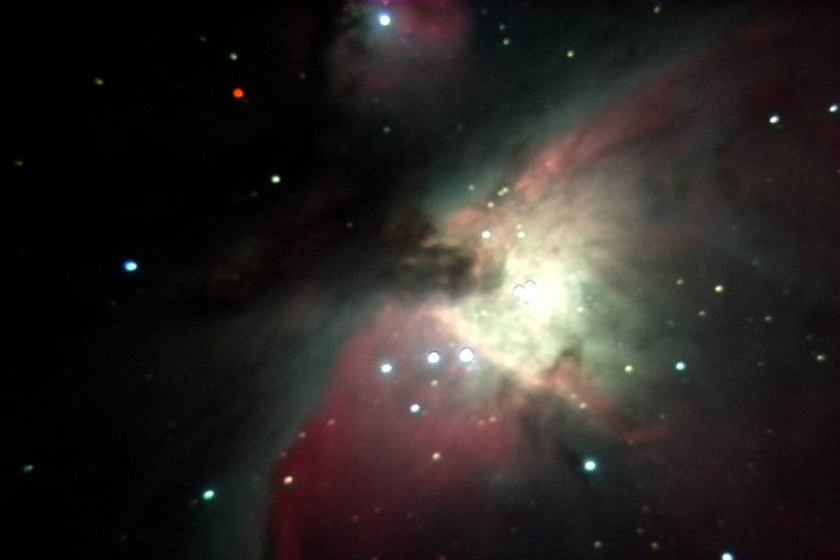
The reducer only yields f/3.3 images when the image is a focused
at a specific distance from the reducer (see Celestron
f/6.3 Focal Reducer). Looking at the separation of stars
in my images I have calculated the focal length of the reducer to be
85mm. This means f/3.3 is achieved when the chip is 57mm from
the reducer. I have taken images with the CFW8 directly
coupled to the SBIG ST-7E and attached to the reducer via the 7mm
adapter. This setup places the CCD chip 49mm behind the
reducer which results in a focal reduction of R=0.42 or f/4.2.
The image of M42 that I
obtained at f/4.2 shows no sign of vignetting. As the CCD chip
should not be placed more than 57mm from the focal reducer it is not
possible to use a flip mirror between the reducer and the CCD
camera. Fortunately, the reducer provides the CCD chip with a
large FOV so it is relatively easy to find images with the LX200
GOTO in high precision mode.
There is an excellent review
of the Meade f/3.3 focal reducer, together with the Optec f/3.3
reducer on Chris Vedeler's site.
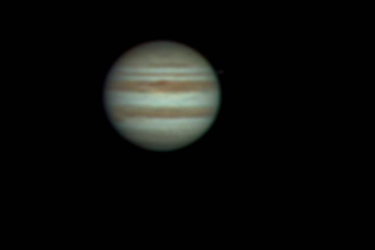
The Meade 2x Telenegative is inserted into the eyepiece holder of
the LX10 or LX200. Eyepieces or CCD cameras can then be
inserted into the telenegative. The telenegative increases the
focal length of the telescope which is extremely useful for imaging
planets where a long focal length is required to increase the size
of the planet on the CCD chip and spread the light out so that
minimum duration exposures are not saturated. The increase in
focal length depends on the distance of the CCD chip from the
telenegtive lens. The increase is governed by the formula M =
1 + (D/F) where M magnifcation factor of the focal length, D is the
distance of the CCD chip from the telenegative lens and F is the
focal length of the telenegative. This implies the further the CCD
chip is from the telenegative the greater the increase in focal
length. In reality the telenegative is designed to work best
when the CCD chip is close to the distance that yields a
magnification factor of 2. However, how close the chip is to
this distance does not seem to be so critical as for a focal redcuer.
When I attach an MX516 and True Technology Flip Mirror to the
telenegative I get a magnifcation factor of 3 giving an f-ratio of
f/30. When I attach the SBIG ST-7E, CFW8 and True Technology
flip mirror I get a magnification of 4 because the CCD chip is
further away from the telenegative lens. This yields an
f-ratio of f/40. The f/40 setup seems to yield very acceptable
images. Take a look at my f/40 image of Jupiter.
The
Robofocus is the electric focuser I use on my Takahashi TOA-130.
It is capable of very accurate focusing (to within less than 0.001
of an inch). It can be manually operated from the supplied
hand controller but it can also be attached directly to a PC via a
serial port which enables software controlled automated focusing.
I use the freeware
FocusMax
software on my PC to perform automated focusing with Robfocus.
This has worked extremely well for me providing reliable and
accurate focusing in my automated imaging sessions.
The
TAKometer Rotator from Astrodon fits Takahashi refractors with a
4 inch focus tube and enables automatic rotation of the CCD camera
from your PC during an imaging session. This accessory makes
it really straightforward to rotate the CCD camera to the required
angle to find a guide star. It is an essential piece of
equipment for automated imaging sessions where you may be imaging
several different targets at different position angles and also have
a meridian flip where the camera needs to be rotated 180 degrees
after the flip to maintain the same position angle and reacquire the
original guide star.
The Flip Flat from
Alnitak Astrosystems is a
circular paddle that contains an evenly illuminated light panel
which covers the OTA opening of a refractor in place of the dust
cover. It is motorized and so can be opened for imaging and
closed for flat fielding
under the control of automated imaging software. This makes
taking flat field images as part of an
automated imaging
session very easy.
 An
electric focuser allows you to adjust the focus of your telescope
without touching the manual focusing knob. This means you can
look at an object through the eyepiece and focus the telescope
without the vibration caused when you turn the manual knob.
This makes it much easier to achieve the correct focus. An
electric focuser also allows very fine focussing adjustments which
it makes it particularly useful for CCD imaging where the telescope
has to be focussed very accurately. An
electric focuser allows you to adjust the focus of your telescope
without touching the manual focusing knob. This means you can
look at an object through the eyepiece and focus the telescope
without the vibration caused when you turn the manual knob.
This makes it much easier to achieve the correct focus. An
electric focuser also allows very fine focussing adjustments which
it makes it particularly useful for CCD imaging where the telescope
has to be focussed very accurately.
The standard JMI Motofocus is very easy to install. It is
basically an electric motor that sits on top of the manual knob and
turns it when you operate the Motofocus handcontroller. The
handcontroller is attached to the electric motor by means of short
cable. This allows you to change focus without touching the
telescope and causing vibration. The handcontroller has two
buttons which allow you to turn the manual knob clockwise or
anticlockwise. It also has a speed control which allows you to
alter the speed with which which the manual knob is turned. By
selecting a slow speed you can achieve the fine focussing of the
telescope that is required for CCD imaging.
In 1998 I purchased a JMI Digital Motofocus. It works on
exactly the same principle as the standard Motofocus described above
but adds a digital counter that goes from 0-999. The counter
lets you know exactly how far you have turned the manual focus knob
each time you use the handcontroller. From 000 to 999 on the counter
represents 10 turns of the manual focus knob. The distance
between each digit on the least significant counter wheel is marked
off in fifths giving a total of 5000 different counter readouts for
10 turns. This means you know the position of the focus knob
to an accuracy greater than 1/100th of one complete turn.
If you record the readout at various focus positions
(e.g. for each eyepiece, CCD camera etc...) you can get back to that
focus position quickly and accurately on subsequent nights.
This proves really useful for the CCD camera which can take some
time to focus accurately using other methods. With the Digital
Motofocus you just need to accurately focus the CCD camera once
using normal methods, record the readout on the counter and from
then on focussing the camera is as simple as pressing a button on
the handcontroller until the counter shows the correct focus
position. A great timesaver.
There are two main drawbacks that I have noticed with both
the standard and digital models of the JMI Motofocus:
-
When finding an accurate focus for a CCD camera you have to
take a picture, look at the image displayed on the PC, alter the
focus slightly, take another picture, and so on until you get an
image that is correctly focussed. Unfortunately, the PC is
often several feet away from the telescope and the
handcontroller cable is only a few inches long. This
means walking back and forward between the PC and telescope
while focussing. This makes focussing much more difficult
and time consuming than it needs to be. I have solved
this by extending the cable to the handcontroller so that I can
sit by the PC and operate the handcontroller at the same time.
Focussing is now easy! The Motofocus cable plugs in to
the handcontroller using a small headphone jack.
Extending this cable is simply a matter of attaching a headphone
extension lead which supports the small jack plug. These
cables are readily available in most electrical stores.
This problem is also solved by the Digital Motofocus as it
greatly reduces the time necessary to focus the CCD camera (see
above).
-
Once the Motofocus is attached you can no longer turn the
manual knob yourself. This may not sound like a problem,
but with CCD imaging you have to make a big focus shift when you
first attach the camera. This involves several turns of
the manual knob. Even at its highest speed it can take the
Motofocus a long time to accomplish this. Fortunately,
removing the motofocus is similar to removing an eyepiece.
You simply undo its retaining screw (which can be done by hand)
and pull it off. This allows you to operate the manual
knob as normal. This workaround cannot easily be used
with the Digital Motofocus. If you have recorded the
counter readout at various focus positions and then remove the
Motofocus to turn the manual knob, you will have to work out new
counter values for the focus positions when you replace the
Motofocus. This is because the Motofocus has no idea how
far you turned the knob yourself. You should never remove
the Digital Motofocus unless you absolutely have to. The
time taken to perform a large focus shift using the Motofocus is
much less than having to work out those focal positions again!
The JMI Digital Motofocus can also be attached to the LX200.
In fact you can plug it directly into the focuser port on the LX200
control panel. This allows it to be controlled via the LX200
handcontroller instead of using the separate JMI handcontroller.
 The
JMI NGFS Crayford Focusser attaches to the SCT threads on the visual
back of the LX200. It can very precisely move an
eyepiece/camera a small number of centimetres towards or away from
the telescope, This means that you can achieve a rough focus
using the manual focus knob and then use the NGFS to achieve a
critical focus. The advantage of using the NGFS to reach
critical focus is that it can be more precisely controlled than the
focus knob. This lets you make smaller changes to the focus
than would otherwise be possible. Also, as the mirror is not
moved to achieve critical focus, the image will not shift in the
eyepiece or CCD chip while making the final adjustments. This
makes it much easier to detect when critical focus has been
achieved. The
JMI NGFS Crayford Focusser attaches to the SCT threads on the visual
back of the LX200. It can very precisely move an
eyepiece/camera a small number of centimetres towards or away from
the telescope, This means that you can achieve a rough focus
using the manual focus knob and then use the NGFS to achieve a
critical focus. The advantage of using the NGFS to reach
critical focus is that it can be more precisely controlled than the
focus knob. This lets you make smaller changes to the focus
than would otherwise be possible. Also, as the mirror is not
moved to achieve critical focus, the image will not shift in the
eyepiece or CCD chip while making the final adjustments. This
makes it much easier to detect when critical focus has been
achieved.
|


